Difference between revisions of "Using buses in a schematic"
| Line 29: | Line 29: | ||
[[File:bus6.jpg]] | [[File:bus6.jpg]] | ||
| − | While it is convenient to deal with a group of wires as a bus rather than drawing the individual wires, it will usually be necessary at some point to draw the individual wires. For example, when you need to add ibufs with Pad locations to the individual wires. | + | While it is convenient to deal with a group of wires as a bus rather than drawing the individual wires, it will usually be necessary at some point to draw the individual wires. For example, when you need to add '''ibufs''' with Pad locations to the individual wires. |
| − | To reference one wire which is part of a bus you can add a bus tap to the bus. Suppose you have a bus labeled x(7:0) as below and you want to attach ibufs to the lower 5 bits to connect them to switches and you want to tie the upper 3 bits high. | + | To reference one wire which is part of a bus you can add a bus tap to the bus. Suppose you have a bus labeled x(7:0) as below and you want to attach '''ibufs''' to the lower 5 bits to connect them to switches and you want to tie the upper 3 bits high. |
[[File:bus7.jpg]] | [[File:bus7.jpg]] | ||
| Line 39: | Line 39: | ||
[[File:bus8.jpg]] | [[File:bus8.jpg]] | ||
| − | Note that you will get an error if you check your schematic at this point because you have drawn a wire named XLXN_?? to a bus tap for a bus named x(7:0). Wires connected to bus taps must be labeled as members of the bus. In this case the wire must be labeled x(7), x(6), ... , x(1) or x(0). | + | Note that you will get an error if you check your schematic at this point because you have drawn a wire named XLXN_?? to a bus tap for a bus named x(7:0). Wires connected to bus taps must be labeled as '''members''' of the bus. In this case the wire must be labeled x(7), x(6), ... , x(1) or x(0). |
You can create all the bus taps and wires, and then conveniently label the bus member wires using the "Increment the name" option. | You can create all the bus taps and wires, and then conveniently label the bus member wires using the "Increment the name" option. | ||
| Line 45: | Line 45: | ||
[[File:bus9.jpg]] | [[File:bus9.jpg]] | ||
| − | If you must connect a wire which has a label other than a bus member to a bus tap or change the name of a bus, you will need to use a buffer symbol: buf. The buf (not ibuf nor obuf) symbol passes its input to the output; it implements the identity function, f(x)=x. This has no real purpose except to allow you to connect two nets that have different labels in the schematic. | + | If you must connect a wire which has a label other than a bus member to a bus tap or change the name of a bus, you will need to use a buffer symbol: '''buf'''. The '''buf''' (not '''ibuf''' nor '''obuf''') symbol passes its input to the output; it implements the identity function, f(x)=x. This has no real purpose except to allow you to connect two nets that have different labels in the schematic. |
[[File:bus10.jpg]] | [[File:bus10.jpg]] | ||
| − | In the schematic above, it was possible to name the wire connected to the VCC symbol, x(7), but in order to make the other bus members, x(6) and x(5), high we needed to add buf symbols since we could not have a net with all three names (or even two names). | + | In the schematic above, it was possible to name the wire connected to the VCC symbol, x(7), but in order to make the other bus members, x(6) and x(5), high we needed to add '''buf''' symbols since we could not have a net with all three names (or even two names). |
[[File:bus11.jpg]] | [[File:bus11.jpg]] | ||
| − | Note is that it is not essential to draw the bus taps. When you label a wire as a bus member (e.g. happy(2)) it is automatically associated with the bus (happy). The schematic above will work just as well as the one preceding it. However, it may be easier for someone else (or you) to understand your schematic if it has bus taps. | + | Note is that it is not essential to draw the bus taps. When you label a wire as a bus member (e.g. '''happy(2)''') it is automatically associated with the bus ('''happy'''). The schematic above will work just as well as the one preceding it. However, it may be easier for someone else (or you) to understand your schematic if it has bus taps. |
| − | You can read more about naming conventions for buses in the Help Topics under the Help menu. One important point to remember is that you can not have a bus and wire by the same name within a schematic. That is, you can not have both a wire labeled "BB" and a bus labeled "BB(0:4)." | + | You can read more about naming conventions for buses in the Help Topics under the Help menu. '''One important point''' to remember is that you can not have a bus and wire by the same name within a schematic. That is, you can not have both a wire labeled "BB" and a bus labeled "BB(0:4)." |
When you simulate, the bus will appear as a single line in the Waveform Viewer. By right clicking on the bus on the left you can have the value of the bus displayed in various formats. Below the value of bus x(15:0) is first displayed as an unsigned integer and then as a hexadecimal integer. | When you simulate, the bus will appear as a single line in the Waveform Viewer. By right clicking on the bus on the left you can have the value of the bus displayed in various formats. Below the value of bus x(15:0) is first displayed as an unsigned integer and then as a hexadecimal integer. | ||
| Line 62: | Line 62: | ||
[[File:bus13.jpg]] | [[File:bus13.jpg]] | ||
| + | |||
| + | |||
| + | |||
| + | The CMPE100 Web: | ||
| + | Copyright 2011; Department of Computer Engineering, University of California, Santa Cruz. | ||
Latest revision as of 23:31, 23 March 2011
A bus is a group of wires representing a bit vector. Rather than drawing and/or labeling the individual wires in a schematic, you can draw a single "bus wire" to represent all of the wires.
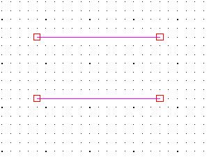
Assume you have drawn two wires in your schematic as below.
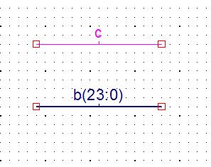
If you now label the top one "c" and the bottom one "b(23:0)" you'll find that the bottom one becomes thicker.
The wire labeled "b(23:0)" is now a bus representing 24 wires.
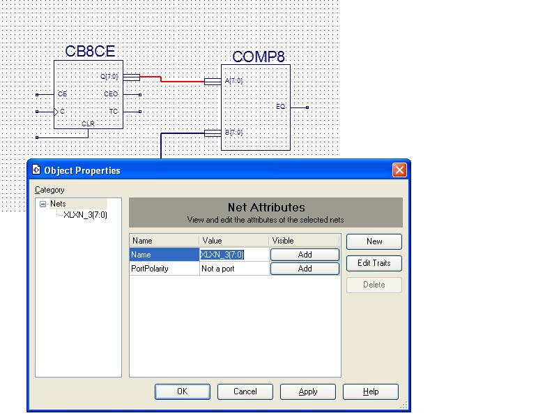
Sometimes you'll find symbols (or create them) that have thick pins labeled with a bus name. When you draw a wire from such a pin you'll be drawing a bus wire. Below two wires have been drawn. As you can see from the "Object properties" window for the selected bus, it has been automatically named "XLXN_3(0:7)" since it is a bus.
It's important that the dimensions and bit order ((7:0) is different from (0:7)) match when connecting buses to pins. Use "Check Schematics" under the Tool menu to find these errors.
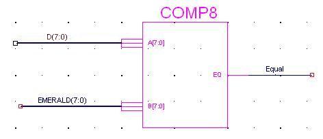
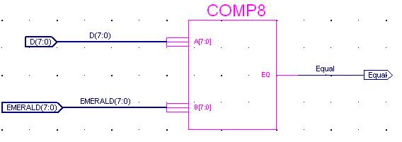
If you have a schematic with buses as inputs or outputs such as the one below,
just add I/O markers to the buses. The I/O marker will be given the bus label.
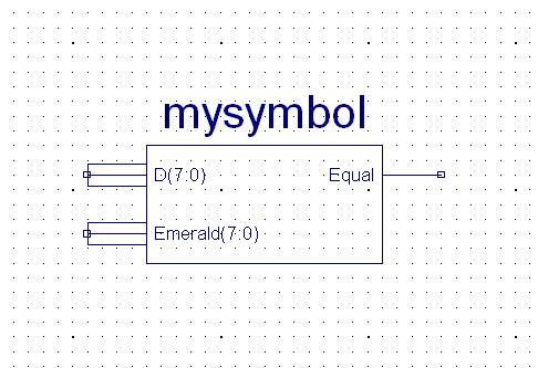
When you create a symbol from a schematic that has an I/O marker with a bus label, your symbol will have a bus pin for that I/O marker.
While it is convenient to deal with a group of wires as a bus rather than drawing the individual wires, it will usually be necessary at some point to draw the individual wires. For example, when you need to add ibufs with Pad locations to the individual wires.
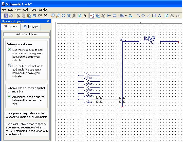
To reference one wire which is part of a bus you can add a bus tap to the bus. Suppose you have a bus labeled x(7:0) as below and you want to attach ibufs to the lower 5 bits to connect them to switches and you want to tie the upper 3 bits high.
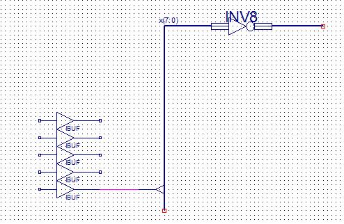
After clicking on the Wire icon select the option "Automatically add a bus tap between a bus and the wire." Then when you draw a wire from the symbol pin to the bus, a "bus tap" will be added to the bus.
Note that you will get an error if you check your schematic at this point because you have drawn a wire named XLXN_?? to a bus tap for a bus named x(7:0). Wires connected to bus taps must be labeled as members of the bus. In this case the wire must be labeled x(7), x(6), ... , x(1) or x(0).
You can create all the bus taps and wires, and then conveniently label the bus member wires using the "Increment the name" option.
If you must connect a wire which has a label other than a bus member to a bus tap or change the name of a bus, you will need to use a buffer symbol: buf. The buf (not ibuf nor obuf) symbol passes its input to the output; it implements the identity function, f(x)=x. This has no real purpose except to allow you to connect two nets that have different labels in the schematic.
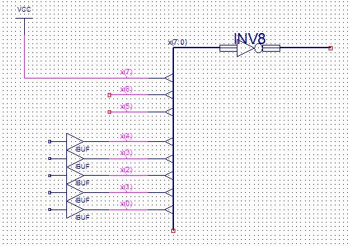
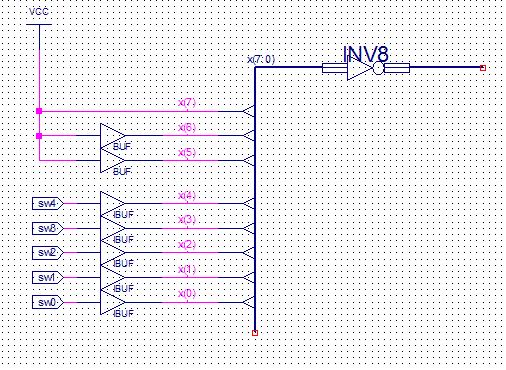
In the schematic above, it was possible to name the wire connected to the VCC symbol, x(7), but in order to make the other bus members, x(6) and x(5), high we needed to add buf symbols since we could not have a net with all three names (or even two names).
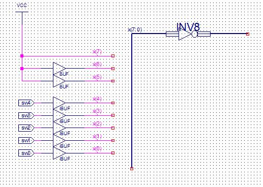
Note is that it is not essential to draw the bus taps. When you label a wire as a bus member (e.g. happy(2)) it is automatically associated with the bus (happy). The schematic above will work just as well as the one preceding it. However, it may be easier for someone else (or you) to understand your schematic if it has bus taps.
You can read more about naming conventions for buses in the Help Topics under the Help menu. One important point to remember is that you can not have a bus and wire by the same name within a schematic. That is, you can not have both a wire labeled "BB" and a bus labeled "BB(0:4)."
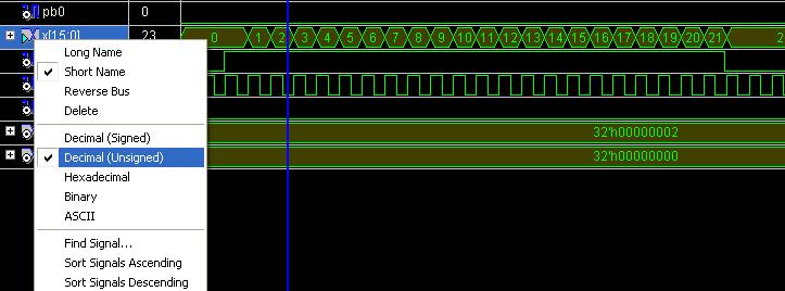
When you simulate, the bus will appear as a single line in the Waveform Viewer. By right clicking on the bus on the left you can have the value of the bus displayed in various formats. Below the value of bus x(15:0) is first displayed as an unsigned integer and then as a hexadecimal integer.
The CMPE100 Web: Copyright 2011; Department of Computer Engineering, University of California, Santa Cruz.
